James (Junior Hardware Engineer)
I am working on integrating some sensors with our new IoT module, and I keep seeing UART mentioned in the documentation. Could you help me understand what makes it different from other communication protocols?
Adam (Senior Systems Engineer)
UART, or Universal Asynchronous Receiver-Transmitter, is a communication protocol for sending data between two devices. Unlike protocols like SPI or I2C, which use separate clock lines for synchronization, UART operates asynchronously. It requires just two wires – TX (Transmit) and RX (Receive) – for bidirectional communication. Its simplicity makes it a go-to for many embedded systems.
James (Junior Hardware Engineer)
That sounds straightforward, but how does it ensure accurate data transfer without a clock signal?
Adam (Senior Systems Engineer)
Good question! In UART, both devices must pre-agree on a baud rate—the speed of communication in bits per second. Each data packet is framed with a start bit (to mark the beginning of a transmission) and one or more stop bits (indicating the end). Additionally, an optional parity bit provides basic error detection. This synchronization ensures the data is sampled accurately, even without a shared clock line.
James (Junior Hardware Engineer)
I see! I also noticed that our cellular IoT modules use UART for configuration and debugging. Is that a common use case?
Adam (Senior Systems Engineer)
Absolutely! UART is commonly used for these tasks because it’s simple, reliable, and available on nearly all microcontrollers. For example, many cellular IoT modules support AT commands over UART for configuration. It is also used for debugging, logging, and firmware updates via bootloaders. Since UART doesn’t need additional clocks or complex wiring, it’s ideal for these applications.
Understanding UART- Universal Asynchronous Receiver-Transmitter
In the IoT connectivity landscape, UART (Universal Asynchronous Receiver-Transmitter) is a fundamental protocol that enables seamless device-to-device interaction.
UART is a hardware communication protocol that enables asynchronous serial communication between devices. Unlike other communication protocols, UART is valued for its simplicity – it requires just two wires for bidirectional communication: one for transmitting (TX) and one for receiving (RX).
Core Components of UART Communication
Data Frame Structure in UART Communication
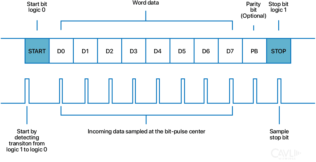
Start Bit:
Each data frame begins with a start bit. It is always a logic level 0 (low voltage). The start bit signals the receiver that a data frame is about to begin, allowing it to prepare for sampling the data.
Data Bits:
Following the start bit are the data bits, ranging from 5 to 9 bits in length. These bits represent the information being transmitted, such as sensor data, commands, or characters. The number of data bits is configurable based on the communication requirements.
Parity Bit (Optional):
An optional parity bit may be included for error detection. Parity can be either even (the total number of 1s in the data bits, including the parity bit, is even) or odd (the total number of 1s is odd). If used, it helps detect single-bit errors during transmission.
Stop Bit(s):
One or two stop bits are added at the end of the data frame. These are always logic level 1 (high voltage) and indicate the end of the data packet. The stop bit ensures there’s enough spacing between consecutive frames, allowing the receiver to reset and prepare for the next data frame.
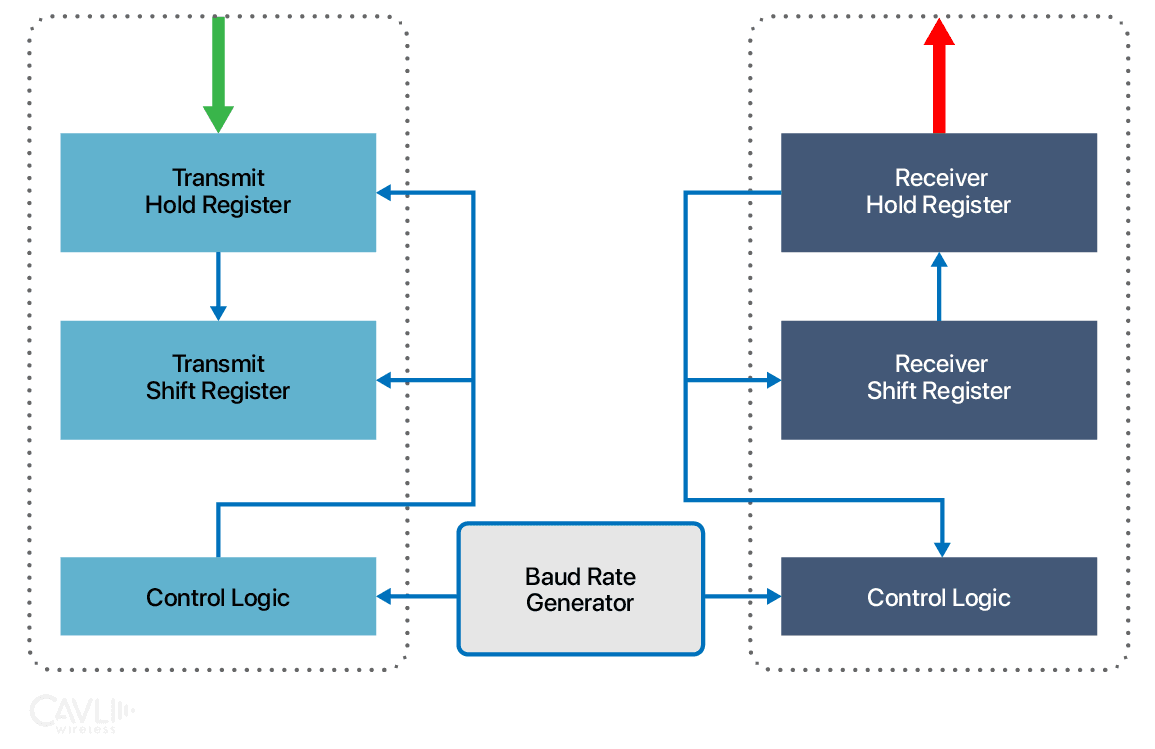
Transmitter (TX Line):
The transmitter in a UART system is responsible for sending data. It takes parallel data from the transmitting device (such as a microcontroller) and converts it into serial form for transmission. To ensure accurate communication, the transmitter adds a start bit and one or more stop bits to frame the data. It also handles the timing of data transmission according to the pre-agreed baud rate, ensuring the receiving device can interpret the data correctly.
For example, the TX line in a UART system efficiently converts data into a serial format for transmission. When a device needs to send data, it starts with a byte of parallel data, such as 0b10110101. The transmitter takes this 8-bit parallel data and converts it into a stream of individual bits 1 → 0 → 1 → 1 → 0 → 1 → 0 → 1, sending them one at a time over the single TX wire bit by bit.
Framing Process in UART:
To ensure the data is interpreted correctly, the transmitter wraps each byte in a frame. For example, consider the parallel data 0xA5 (binary: 10100101):
- A start bit (0) is added at the beginning of the frame to signal the start of transmission.
- The data bits (10100101) are transmitted as they are.
- An optional parity bit (e.g., 1) is included for error checking, depending on configuration.
- One or two stop bits (1) are appended at the end to signal the end of the frame and provide spacing before the next frame begins.
Timing Control:
Precise timing is critical in UART communication to ensure synchronization between the transmitter and receiver. The baud rate determines how fast the data is transmitted. For instance, at a baud rate of 9600, each bit is sent in 1/9600 seconds or approximately 104.17 microseconds. The transmitter maintains this timing for consistent bit spacing, allowing the receiver to sample each bit accurately at the agreed-upon rate. This shared understanding of timing eliminates the need for an external clock line, making UART communication simple yet effective.
Receiver (RX Line)
The RX line, in UART communication, ensures incoming serial data is accurately decoded and delivered to the receiving device. It uses a combination of advanced sampling techniques, frame processing, and serial-to-parallel conversion to rebuild and validate the transmitted data.
The receiver's role is to accept incoming serial data from the transmitter. It samples the incoming data at precise intervals based on the shared baud rate. The receiver identifies and removes the start bit and stop bits and optionally checks the parity bit for errors. Finally, it converts the serial data back into parallel form for processing by the receiving device.
Sampling Process
To minimize errors, the receiver samples each incoming bit multiple times. For example, at a baud rate of 9600, the duration of each bit (bit period) is approximately 104.17 microseconds. The receiver divides this period into 16 intervals, with each sample taken roughly every 6.51 microseconds. Once all samples for a bit are collected, the receiver uses a majority voting mechanism to determine whether the bit is a 1 or 0. This method helps reject noise and ensures accurate reception, even in less-than-ideal transmission conditions.
Frame Processing
Once the RX line has successfully sampled and identified each bit, it processes the received frame to extract the data. For example, consider the frame 0 10100101 1 1:
- The start bit (0) is detected, signaling the start of the frame.
- The data bits (10100101) are read sequentially.
- The parity bit (if present) is checked for errors.
- The stop bit(s) (1 or more) are verified to confirm the frame's integrity.
After processing, the RX line outputs the original data byte—in this case, 0xA5 (binary: 10100101).
Serial-to-Parallel Conversion
To make the data usable for the receiving device, the RX line converts the sequential serial bits back into their original parallel format. The reconstructed byte is then buffered and made available for the processor to read. During this process, any errors detected—such as parity mismatches or framing issues—are flagged, ensuring the system is aware of potential communication problems. By combining robust sampling, structured frame decoding, and reliable conversion mechanisms, the RX line ensures data is received accurately and is ready for immediate use by the receiving system.
Working of UART Protocol
UART (Universal Asynchronous Receiver-Transmitter) is a widely used communication protocol that simplifies data exchange between devices using just two primary lines: TX (Transmit) and RX (Receive). Unlike clocked protocols like SPI or I²C, UART achieves synchronization through pre-agreed settings and structured data framing, making it both simple and versatile.
Synchronization Without a Clock
UART does not use a shared clock line. Instead, it relies on:
Idle State
The communication line is held in an idle state (logic 1) when no data is being transmitted. This allows the receiver to detect the start of a new transmission when the line transitions to a start bit (logic 0).
Predetermined Baud Rate
Before communication begins, the transmitter and receiver must agree on a baud rate, such as 9600 bps or 115200 bps. This rate determines how fast the data is sent and sampled. Both devices must maintain precise timing to ensure successful data transfer, though small mismatches are tolerable.
Error Detection and Reliability
To ensure reliable communication, UART incorporates multiple error detection and control mechanisms:
Framing Error Detection
A framing error occurs if the expected stop bit is missing or corrupted. It indicates a possible synchronization issue or signal noise during transmission.
Overrun and Break Detection
An overrun error occurs if new data arrives before the receiver reads the previous byte, often due to processing delays. A break condition is detected when the line remains low for longer than a frame duration, typically used to signal a deliberate pause or reset in communication.
Flow Control
Hardware Flow Control
Uses RTS (Request to Send) and CTS (Clear to Send) lines to manage data flow between devices, preventing buffer overflows.
Software Flow Control
Implements special characters, like XON/XOFF, to start or pause data transmission dynamically.
Data Conversion and Processing
Serial-to-Parallel and Parallel-to-Serial Conversion
At the transmitter, UART converts parallel data (e.g., an 8-bit byte) into a serial stream of bits for transmission over the TX line. At the receiver, this process is reversed, rebuilding the original parallel data from the incoming serial bits on the RX line.
Buffering for Efficiency
Many UART implementations include transmit (TX) and receive (RX) buffers to temporarily store data. This allows the processor to handle data efficiently without being overwhelmed by high-speed transmissions.
Comparison of UART with SPI and I2C
| Feature | UART | SPI | I2C |
|---|---|---|---|
| Communication Type | Asynchronous, point-to-point | Synchronous, master-slave | Synchronous, multi-master |
| Clock Signal | None | Required (shared clock line) | Required (shared clock line) |
| Number of Wires | 2 (TX, RX) + optional GND | 4+ (MISO, MOSI, SCLK, SS) | 2 (SDA, SCL) |
| Speed | Variable (Standard: 115.2 kbps - 1 Mbps; HSUART: up to 12 Mbps) | High (Standard: up to 20 Mbps; Enhanced: 50+ Mbps) | Moderate (Standard: 100 kbps; Fast Mode Plus: 1 Mbps; High-Speed: 3.4 Mbps; Ultra-Fast: 5 Mbps) |
| Distance | Short (TTL: 1-3 m; RS-232: ~15 m; RS-485: ~1200 m) | Very short (~1 m, clock-dependent) | Short (~30 cm); With buffers/repeaters: up to several meters |
| Full-Duplex | Yes | Yes | No |
| Multi-Master Support | No | Possible with additional hardware/software control | Yes |
| Multi-Slave Support | Limited (via RS-485 or software handling) | Yes | Yes |
| Error Detection | Parity bit (optional), framing error | None | Acknowledge (ACK/NACK) |
| Flow Control | Optional (RTS/CTS, XON/XOFF) | None | None |
| Hardware Complexity | Low (point-to-point), Moderate (with flow control) | Moderate (increases with number of slaves) | Low (requires pull-ups and careful design) |
| Power Requirements | Low (active during transmission) | Low-Moderate (clock always active) | Low idle; pull-ups consume continuous power |
| Bus Loading | None | Minimal | High (affected by capacitance) |
| Clock Synchronization | Requires matching baud rates | Synchronized by master clock | Supports clock stretching |
| Applications | Debugging, low-speed data transfer, configuration | High-speed data transfer, sensors | Sensors, EEPROMs, peripherals |
Applications of UART Protocol in the Internet of Things
Device Configuration and Initialization
UART is widely used to configure IoT devices, especially during setup. For example, sending AT commands to Bluetooth, Wi-Fi, or GSM modules to configure network settings.
For example, configuring a Wi-Fi module (e.g., ESP8266) to connect to a specific network using UART commands.
Debugging and Diagnostics
Developers use UART to debug IoT devices by sending logs and error messages to a serial terminal.
For example, a microcontroller-based IoT device outputs diagnostic information (e.g., sensor readings and error states) to a PC for monitoring via a USB-to-UART bridge.
Firmware Updates
UART interface is used for firmware updates in IoT devices via bootloaders. While UART is not inherently an OTA mechanism, it can act as the communication medium in scenarios where firmware updates are delivered wirelessly (over-the-air) and then transferred to a microcontroller or IoT device using the UART interface.
For example, updating a microcontroller’s firmware using a UART-based bootloader utility to load the new code from a host system.
Home Automation Systems
UART connects smart home components, such as light controllers, thermostats, and door sensors, to a central hub or gateway.
For example, a UART-enabled cellular IoT module in a smart home hub transmits real-time sensor data, enabling remote control of lights, locks, and HVAC systems without relying on Wi-Fi.
IoT Gateways and Edge Devices
UART enables communication between IoT gateways and edge devices for local data processing or aggregation before sending data to the cloud.
For example, an IoT gateway reads sensor data from multiple UART-connected devices, processes it, and transmits it to a cloud server over Ethernet or Wi-Fi.
Interfacing with GPS Modules
Many IoT applications use UART to connect GPS modules for location tracking in real-time.
For example, a vehicle tracking system reads GPS data (latitude, longitude, speed) from a UART-enabled GPS module to monitor fleet movements.
Smart Agriculture
UART interfaces with environmental sensors in smart agriculture systems, collecting data for precision farming.
For example, soil moisture sensors connected via UART relay data to an IoT gateway for irrigation control.
Energy Monitoring and Smart Grid Systems
UART is used to connect energy meters and power monitoring systems to IoT platforms for data analysis and reporting.
For example, a smart energy meter transmits power usage data to a central hub via UART for cloud-based monitoring.
Closing Notes
UART (Universal Asynchronous Receiver-Transmitter) has stood the test of time as a foundational communication protocol in embedded systems and IoT devices. Its simplicity, minimal hardware requirements, and widespread adoption make it a go-to solution for developers working on point-to-point communication. From configuring IoT modules and debugging systems to interfacing with sensors and actuators, UART remains a versatile tool that meets the needs of a wide range of applications.
Amusing Tech Chronicles
Facts and Anecdotes Related to this Edition of Wireless By Design

The Double Pipeline
Picture UART as a double pipeline system. One pipeline (TX) transports water (data) from a reservoir to a factory, while the other pipeline (RX) sends treated water (response data) back to the reservoir. Both pipelines operate simultaneously, ensuring continuous two-way flow. The start bit is the opening of a valve to begin water flow, while the stop bit is the valve closing to end the process.

The Theater Stage
Think of UART as a theater production. The start bit is like the curtain rising, signaling the audience (receiver) that the performance (data) is beginning. The data bits are the actors delivering the main content of the show. The stop bit is the curtain falling at the end of the scene, providing a pause before the next act begins. If there’s a parity bit, it’s the stage manager ensuring the props (data) are all in place, and nothing is missing before the show proceeds!

The Double Conveyor Belt System
Think of UART as a factory with two conveyor belts running side by side. One belt (TX) delivers raw materials (data bits) to the processing machine, while the other belt (RX) brings finished products (response data) back to the packaging area. Both belts operate simultaneously, moving independently but in a coordinated rhythm set by the baud rate. The start bit is the machine operator signaling "start the belt," and the stop bit ensures no items are left in transit.
Go Beyond and Explore
How Full-Duplex Works in UART?
- TX Line (Transmit): Responsible for sending data from the transmitting device to the receiving device.
- RX Line (Receive): Dedicated to receiving data from another device’s TX line.
- While one device is sending a stream of data (e.g., sensor readings) over its TX line, it can simultaneously listen for incoming data (e.g., control commands) on its RX line.
- This independent operation is especially useful in scenarios where real-time two-way communication is necessary, such as debugging or exchanging commands and responses between devices.
-
Unlike half-duplex communication protocols (e.g., RS-485 or certain SPI configurations), there is no need for devices to "take turns" sending and receiving data. This saves time and improves efficiency in applications where bidirectional data exchange is frequent.
What is the Connection Between RS-232, RS-485, and UART
UART and RS-232:
- UART provides the logic-level signals (e.g., 0V for logic 0 and 3.3V or 5V for logic 1).
- To communicate over RS-232, a level shifter (e.g., a MAX232 IC) converts these UART signals to RS-232 voltage levels.
- RS-232 simply extends the reach of UART signals by adding higher voltage levels for robustness over longer cables.
- UART provides the logic-level signals.
- An RS-485 transceiver converts UART’s TX and RX lines into differential signals required for RS-485 communication.
- RS-485 extends UART’s reach by allowing multiple devices and longer distances while offering superior noise immunity.
- RS-232 is suitable for point-to-point communication over moderate distances.
- RS-485 excels in multi-device communication over long distances with high noise resistance.
UART and RS-485:
Key Differences:
What are the Alternatives to UART?
-
I²C (Inter-Integrated Circuit)
- Key Features:
- Synchronous protocol (requires a clock line).
- Supports multi-master and multi-slave communication.
- Uses only two wires: SDA (data) and SCL (clock).
- Advantages over UART:
- Allows multiple devices on the same bus with unique addresses.
- Suitable for short-distance communication between multiple ICs.
- Disadvantages compared to UART:
- Lower speeds compared to UART in many implementations.
- More complex to implement in software.
- Key Features:
-
SPI (Serial Peripheral Interface)
- Key Features:
- High-speed synchronous protocol.
- Requires multiple wires: MOSI (Master Out Slave In), MISO (Master In Slave Out), SCLK (Clock), and CS (Chip Select).
- Advantages over UART:
- Faster data transfer speeds (up to 50 Mbps or more).
- Full-duplex communication.
- Disadvantages compared to UART:
- Point-to-point or multi-slave only, requiring a unique chip selection for each slave device.
- Requires more wires, increasing complexity.
- Key Features:
-
USB (Universal Serial Bus)
- Key Features:
- Standardized interface for high-speed communication and power delivery.
- Supports host-device communication with a complex protocol stack.
- Advantages over UART:
- Faster speeds (up to 40 Gbps for USB 4).
- Plug-and-play compatibility with modern devices.
- Can connect multiple devices through hubs.
- Disadvantages compared to UART:
- More complex to implement.
- Consumes more power.
- Key Features:
-
CAN (Controller Area Network)
- Key Features:
- Designed for robust communication in automotive and industrial environments.
- Uses two differential signals (CAN_H and CAN_L).
- Advantages over UART:
- Supports multi-node communication with high noise resistance.
- Ideal for real-time control systems.
- Disadvantages compared to UART:
- More complex to implement.
- Typically slower than USB and SPI.
- Key Features:
Author

Drishya Manohar
Sr. Associate - Content Marketing