James, Jr. Network Engineer
Hey Adam, I'm working on integrating multiple sensors into our new IoT device, and I'm struggling to choose between I²C and SPI protocol. Some documents call it a protocol, others an interface. What exactly is it?
Adam, Sr. Network Engineer
Ah, that's a common source of confusion! acts as both - it's a serial communication protocol that defines how devices should talk to each other, and it's also a physical interface specification that defines how to connect them using just two wires. Unlike SPI, which needs separate lines for each device, the I²C communication protocol can connect lots of sensors using just two lines.
I2C
James, Jr. Network Engineer
Can you explain to me how it manages multiple device communications with just two wires without causing any congestion?
Adam, Sr. Network Engineer
That's one of I2C's clever features! The two wires - SDA for data and SCL for clock - create a shared bus that multiple devices can connect to. The protocol part of I²C defines how devices take turns using these lines through addressing and arbitration. It also has built-in traffic management, with each device having a unique address and a protocol for handling multiple communications at once. Plus, devices can even signal when they need more time to process data.
James, Jr. Network Engineer
But what about data speed? Won't all devices sharing two wires create a bottleneck in the entire network?
Adam, Sr. Network Engineer
While I²C bus communication might not match SPI's raw speed, it offers different speed modes up to 5 Mbit/s in Ultra-Fast mode(unidirectional). For most sensors and EEPROMs, even the standard 100 kbit/s mode is ample for data transmission. To learn more about the I²C communication protocol, follow this blog.
What is the I²C Protocol?
I²C (Inter-Integrated Circuit) is a serial, multi-master, multi-slave, packet-switched, single-ended, two-wire communication protocol developed by Philips Semiconductors (now NXP) in 1982. It is also referred to as IIC. It operates both in the data link layer and physical layer of the OSI model, providing a standardized method for intra-board communication between integrated circuits. The I²C communication protocol provides the following physical layer characteristics:
- Operating Voltage Ranges:1.8V to 5.5V
- Maximum Bus Capacitance:400pF
- Addressing Space:7-bit or 10-bit
- Maximum Bus Length: Typically 2-3 meters with specialized setups
The Architecture of I²C Protocol
I²C protocol provides a set of rules for devices to communicate with each other. It ensures the data being sent is understandable by all connected components.
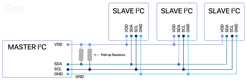
SDA and SCL Lines
I²C Protocol uses two wires for communication, namely:
- SDA (Serial Data Line):Transfers the actual data between devices.
- SCL (Serial Clock Line):It provides the clock signal to synchronize the timing of data transfer, ensuring the sender and receiver are in harmony during communication.
SDA and SCL are open-drain lines or open-collector outputs, meaning devices can pull the line low but require external pull-up resistors to bring the line high. This design ensures that multiple devices can share the same bus without damaging each other.
Pull-Up Resistors
Since SDA and SCL lines are open-drain: They need pull-up resistors to ensure both the lines return to a high voltage state. The pull-up resistors maintain the lines' default high state and enable devices to "pull" the line low to communicate.
Value of Pull-Up Resistors: The resistor selection depends on bus capacitance and speed. It is calculated based on R=tr/Cb, where tr is the rise time and Cb is the bus capacitance. Its value is typically between 1 kΩ and 10 kΩ. Lower values allow faster rise terms but increase power consumption. Higher resistance means slower rise time (good for low-speed buses). Lower resistance allows faster rise time (necessary for high-speed modes).
Bus Capacitance
- Tolerance:The I²C bus communication has a limit on how much capacitance it can tolerate. Typically 400 pF (picoFarads) in standard mode.
- High capacitance: Can slow signal rise times, affecting data integrity and limiting bus speed.
Voltage Levels
The I²C bus protocol is flexible in supporting different voltage levels. For compatibility with various devices.
- Common voltage levels: 3.3V, 5V, and low voltages (e.g., 1.8V in modern devices).
- It ensures all devices on the bus operate at compatible voltage levels or use level shifters to interface between devices with different voltages.
Physical Layer Requirements
- Connection Topology: The I²C bus protocol typically uses a shared bus topology, where all devices connect to the same two wires (SDA and SCL).
- Device Addressing: Each device has a unique address to prevent conflicts on the shared bus.
- Line Length: Shorter wires are preferred to reduce capacitance and noise.
- Shielding and Noise Reduction: In noisy environments, shielded cables or twisted pairs are used to minimize interference.
Working of I²C Communication Protocol
Master-Slave Relationship
The working principle of the Inter-Integrated Communication protocol revolves around how devices communicate with each other on a shared two-wire bus. It uses a master-slave relationship, meaning one device (the master) controls the communication while the others (slaves) respond to its commands. In a single-master system, only one master is present on the bus. It initiates communication and manages the flow of data. In contrast, a multi-master system allows multiple masters. These masters can take turns controlling the bus but should follow strict rules to avoid conflicts.
Start Condition
The I²C bus communication begins with a start condition. The master device generates this signal to alert all devices on the bus. It indicates the SDA line transitions from high to low while the SCL line stays high. This unique pattern signals the start of a new data frame and prepares all devices for communication.
Addressing Mechanism
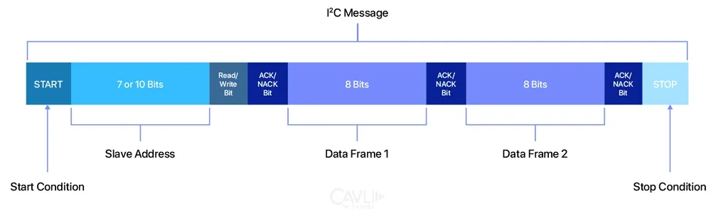
Each device on the bus has a unique address. This address can be either 7 bits long (the commonly used actual range is 0x00 to 0x7F) or 10 bits long (for systems with many devices). When the master wants to talk to a specific slave, it sends out this address first. Only the device with the matching address will respond.
To keep communication orderly, the master provides a clock signal on the SCL line. This signal ensures that all devices on the bus stay in sync. This process is called clock synchronization.
When multiple masters try to use the bus simultaneously, they must determine which one gets the control. It is done through bus arbitration. During arbitration, the masters compare their data bits. The one sending the "lower-priority" bit (a 1 instead of a 0) stops its transmission and waits for the bus to be free again.
This way, the I²C bus protocol ensures smooth and reliable communication, even when multiple devices share the same wires.
Read/Write Bit
Following the address, the master appends a read/write (R/W) bit to indicate the intended direction of data flow:
- 0 (Write): The master wants to send data to the slave.
- 1 (Read): The master wants to receive data from the slave.
This bit ensures that both the master and the slave know their roles in the communication.
ACK/NACK Bits
After each byte of data (including the address), the receiver sends an ACK (Acknowledge) bit to confirm successful reception:
- ACK: The receiving device pulls the SDA line low, signaling the byte was received correctly.
- NACK: If the receiver cannot process the byte (e.g., the device is busy or the address is unmatched), it leaves the SDA line high. A NACK also signals the end of data transfer in read operations.
ACK/NACK bits ensure robust error checking and control during communication.
Data Transfer
Once the address and roles are established, data transfer begins. The master and slave exchange data one byte at a time:
- The sender (master or slave) places 8 bits (1 byte) on the SDA line.
- The receiver reads the byte and sends an ACK or NACK to indicate success or failure.
This process continues until all data is transferred.
Advanced Features Incorporated by I²C Protocol
Clock Stretching
Clock stretching allows a slave device to hold the SCL line low to signal the master that it needs more time to process data.
It is used in:
- Slower peripherals like sensors or microcontrollers need extra time to prepare data.
- Situations where synchronization between fast masters and slow slaves is critical.
For example: Temperature sensors, EEPROMs, etc.
Multi-Master Operation
It allows multiple master devices to share the same I²C bus, each capable of initiating communication. It is used in complex systems where multiple controllers or microcontrollers need access to the same devices. Examples include industrial automation, infotainment systems, and engine control systems.
Bus Arbitration
Bus arbitration ensures that only one master controls the bus at a time by comparing signals on the shared SDA line. Masters transmitting a high-priority (low) bit continue while others withdraw. It ensures that when multiple masters attempt to communicate simultaneously, only one takes control of the bus based on priority.
It is used in multi-master systems to avoid conflicts and ensure smooth communication.
Example: Multi-controller systems with different controllers monitoring the same sensors or sharing access to a single device.
Different Speed Modes
The I²C interface supports various speed modes to cater to different performance requirements:
- Standard Mode (100 kbit/s): Suitable for general applications like home appliances.
- Fast Mode (400 kbit/s): This mode is for fast communication systems that require higher throughput, such as LCDs and EEPROMs.
- Fast-Mode Plus (1 Mbit/s): For advanced systems requiring much faster data transfers. It is becoming increasingly common in modern devices.
- High-Speed Mode (3.4 Mbit/s): For specialized high-speed applications like cameras or advanced sensors in high-performance systems.
- Ultra-Fast Mode (5 Mbit/s): It is unidirectional and used in scenarios where speed is critical and niche applications in cutting-edge technologies.
Where is the I²C Protocol Used?
Sensor Interfaces
The I²C communication protocol is a popular choice for interfacing sensors in electronics. Many sensors, such as accelerometers, gyroscopes, and temperature and humidity sensors, come with built-in I²C interfaces.
Use Cases
- Environmental monitoring systems using temperature and humidity sensors.
- Motion-tracking devices with accelerometers and gyroscopes.
EEPROM Communication
EEPROM (Electrically Erasable Programmable Read-Only Memory) is a non-volatile data storage memory interfaced using I²C for tasks like storing configuration settings. I²C bus protocol is employed to interface EEPROM chips with controllers.
Use Cases
- Storing configuration settings in embedded systems.
- Saving calibration data in industrial instruments.
Real-Time Clocks (RTCs)
I²C protocol interfaces real-time clock modules, which keep track of time even when the main device is powered off.
Use Cases
- Timekeeping in computers and IoT devices.
- Accurate time stamps for logging and scheduling systems.
Display Interfaces
Many displays, especially character LCDs and OLED displays, use the I²C protocol for communication. This simplifies the connection and reduces the number of required pins.
Use Cases
- Wearable devices with small OLED screens.
- Embedded systems displaying status information on LCDs.
Industrial Applications
The I²C communication protocol is widely used in industrial automation and control systems for interfacing sensors, actuators, and monitoring devices, such as temperature and pressure sensors.
Use Cases
- Process control systems using multiple sensors and controllers.
- Factory equipment monitoring temperature, pressure, and other parameters.
Closing Notes
The I²C protocol is a simple yet powerful communication standard that connects multiple devices using just two wires. Its versatility makes it essential for applications ranging from sensor interfaces and EEPROMs to real-time clocks and industrial automation. Features like multi-master operation, clock stretching, and variable speed modes enhance its adaptability for modern systems. The I²C bus protocol efficiency and ease of use make it a favorite among IoT engineers. Whether in consumer electronics, automotive systems, or industrial setups, I²C enables seamless communication between components. By understanding its basics, you can leverage I²C to design everything from simple projects to complex systems in this connected world.
Amusing Tech Chronicles
Facts and Anecdotes Related to this Edition of Wireless By Design

The Train Journey
On a train route, the conductor (master) controls when the train starts and stops (start and stop conditions). At each station (slave), passengers with the right ticket (address match) board or leave the train (data transfer). The conductor checks tickets (ACK/NACK) to ensure everything is in order before proceeding to the next station.

The Classroom
Imagine a classroom with a teacher and students. The teacher is the master. The teacher asks questions (gives commands), and only the student being addressed responds, while the others stay quiet. The teacher also signals when it’s time to stop or move on. This organized communication ensures that everyone understands and participates without confusion.

The Bus Route
The I²C bus communication is like a public bus route. The bus (master) has a fixed path and schedule (SCL clock) and picks up or drops off passengers (data) at stops (slave devices). Each stop has a unique address, so the driver knows exactly where to halt. If a stop isn’t ready, the bus waits (clock stretching) until the passengers are ready to board.
Go Beyond and Explore
What is the difference between I2C and SPI Protocol?
How many slaves can be connected in I2C bus protocol?
- Bus capacitance (limited to about 400pF)
- Power requirements
- Address conflicts (many I2C devices use fixed addresses)
- Signal integrity considerations For most IoT applications, 8-12 devices are a practical limit without using multiplexers or bus buffers.
Does the I2C protocol need pull-up resistors?
- Bus capacitance
- Operating voltage
- communication speed
- For 3.3V systems: 2.2kΩ to 10kΩ
- For 5V systems: 1.8kΩ to 4.7kΩ
Is the I2C bus protocol good for long distances?
- Standard I2C bus communication: typically reliable up to 50cm
- With special considerations (buffers, lower speeds): up to 2-3 meters
- Limitations are due to:
- Capacitance (400pF max)
- Signal integrity
- EMI susceptibility
- For longer distances in IoT applications, solutions include:
- I2C buffers/repeaters
- Converting to differential signaling
- Using alternative protocols like RS-485 for long distances