The Internet of Things (IoT) is rapidly transforming industries like automotive, manufacturing, and agriculture by enabling devices to share real-time data, enhancing automation and efficiency. Communication between these devices has relied on the Controller Area Network (CAN) protocol, especially in automotive applications.
For example, traditional cabling in automobiles involves complex wiring that connects various electronic components directly.
Each function or device requires a separate wire for control and communication, leading to bulky and expensive wiring networks. This not only makes the system less reliable and harder to maintain, but also increases the weight and cost of the vehicle.
What is a CAN Bus?
CAN bus or Controller Area Network bus is a robust messaging protocol designed to allow microcontrollers and devices within a vehicle or other application to communicate with each other without a host computer.
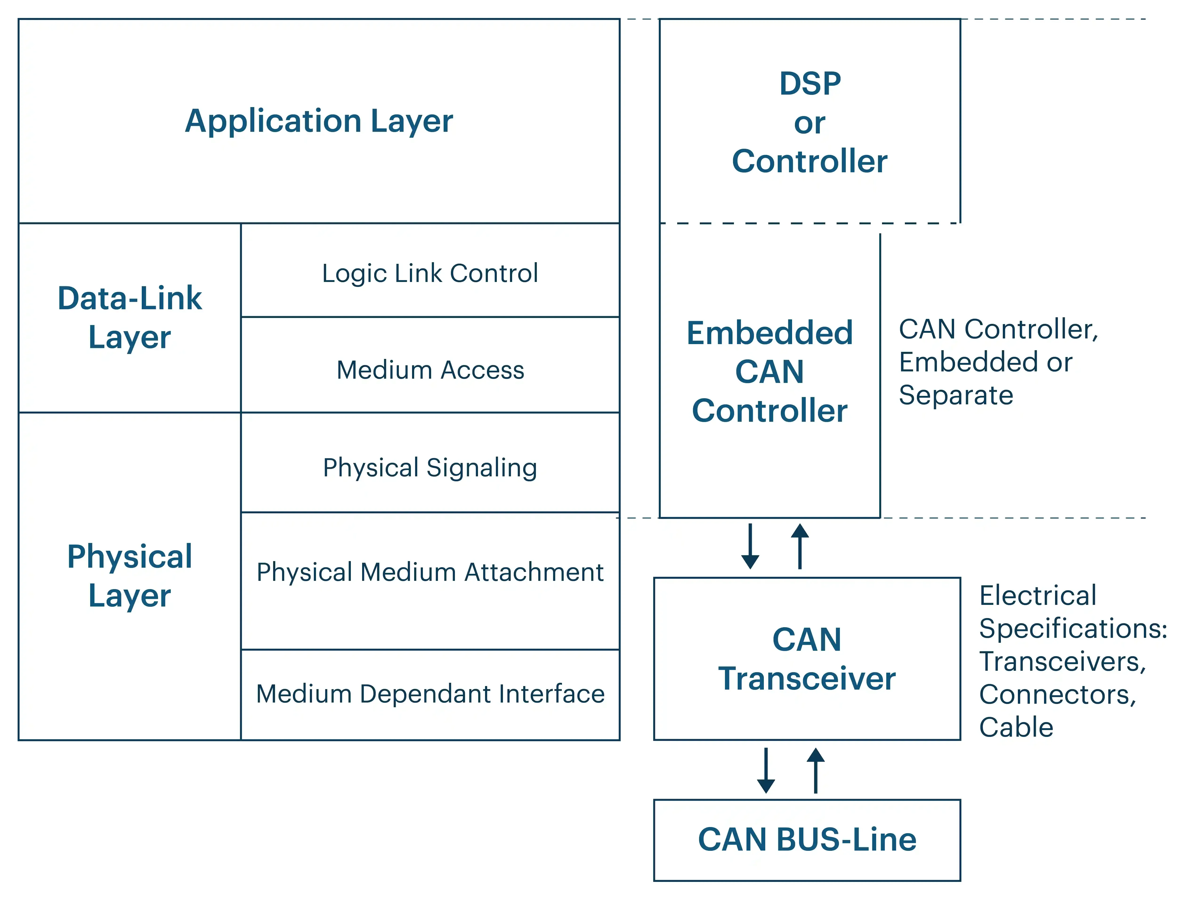
CAN bus protocol was developed to reduce complex wiring, improve reliability, and facilitate real-time data exchange. It helps multiple electronic control units (ECUs) to transmit information efficiently over a single or dual-wire network, significantly streamlining the network architecture in automotive and other industrial applications.
It is designed to allow microcontrollers to communicate with each other's applications without a host computer. It is typically used in automotive and industrial contexts to connect electronic control units (ECUs) and sensors for various systems such as engine management, transmission, brakes, lighting, electronic fuel injection, and in-vehicle entertainment systems, among others.
CAN bus interface is not just a protocol that helps in reducing the heavy wiring in automotive systems; they are also used in various other IoT applications. For example, DeviceNet is an industrial network protocol built on the Controller Area Network (CAN) bus. It utilizes the CAN bus's physical and data link layers to establish communication among networked industrial devices.
DeviceNet adapts CAN for industrial IoT use cases by providing a standardized communication protocol, Common Industrial Protocol (CIP), which operates over the underlying CAN infrastructure. This integration allows DeviceNet to leverage the robust, efficient, and reliable messaging capabilities of the CAN bus while providing a higher-level protocol suited for automation and industrial environments.
CAN bus is also used for agricultural IoT applications. ISOBUS is a protocol that operates on a Controller Area Network (CAN) bus. ISOBUS refers to the ISO 11783 standard, which is an international standard for communication between agricultural equipment and software. This standard ensures that equipment and systems from different manufacturers can communicate effectively using a standardized protocol over the CAN bus.
The Controller Area Network (CAN) bus technology is also used in marine electronics. NMEA 2000, developed by the National Marine Electronics Association (NMEA), interconnects marine sensors, display devices, and actuators such as GPS units, sonar, weather stations, and other marine instruments.
CAN Bus Classification
The below mentioned are some of the CAN Bus classifications. While High-Speed CAN and Low-Speed/Fault-Tolerant CAN are classified based on speed, CAN FD (Flexible Data-Rate) is classified based on the CAN protocol version. CANopen, on the other hand, falls under the classification of Application Layer Protocols based on the application domain of the CAN bus.
High-Speed CAN (ISO 11898-2)
High-speed CAN operates up to 1 Mbps and uses a differential signaling scheme, which helps it resist electromagnetic interference in a noisy environment. It's typically used for critical control applications such as engine management systems, ABS, and other vehicle dynamics and safety controls.
Low-Speed/Fault-Tolerant CAN (ISO 11898-3)
Low-Speed CAN, also known as Fault-Tolerant CAN, speeds up to 125 Kbps and is designed to be more fault-tolerant, allowing communication to continue even if one of the bus lines is damaged. It's used in applications where data transmission speed is less critical but higher fault tolerance is necessary, such as vehicle body control functions like power windows, seats, and mirrors.
CAN FD (Flexible Data-rate)
CAN FD, or Flexible Data-rate, is a classification of the CAN protocol based on data length. In this enhancement of the traditional CAN, CAN FD allows for higher data rates and longer data fields in a frame (up to 64 bytes of data compared to the classic 8 bytes). This makes it more suitable for modern applications requiring faster communication and more data throughput, such as advanced driver-assistance systems (ADAS) and other complex vehicle functions.
CANopen
CANopen is another CAN bus classification based on layering; in this higher-layer protocol, it defines additional features such as device profiles, communication profiles, and application layers that simplify the integration of devices from different manufacturers.
CAN Bus Message Format
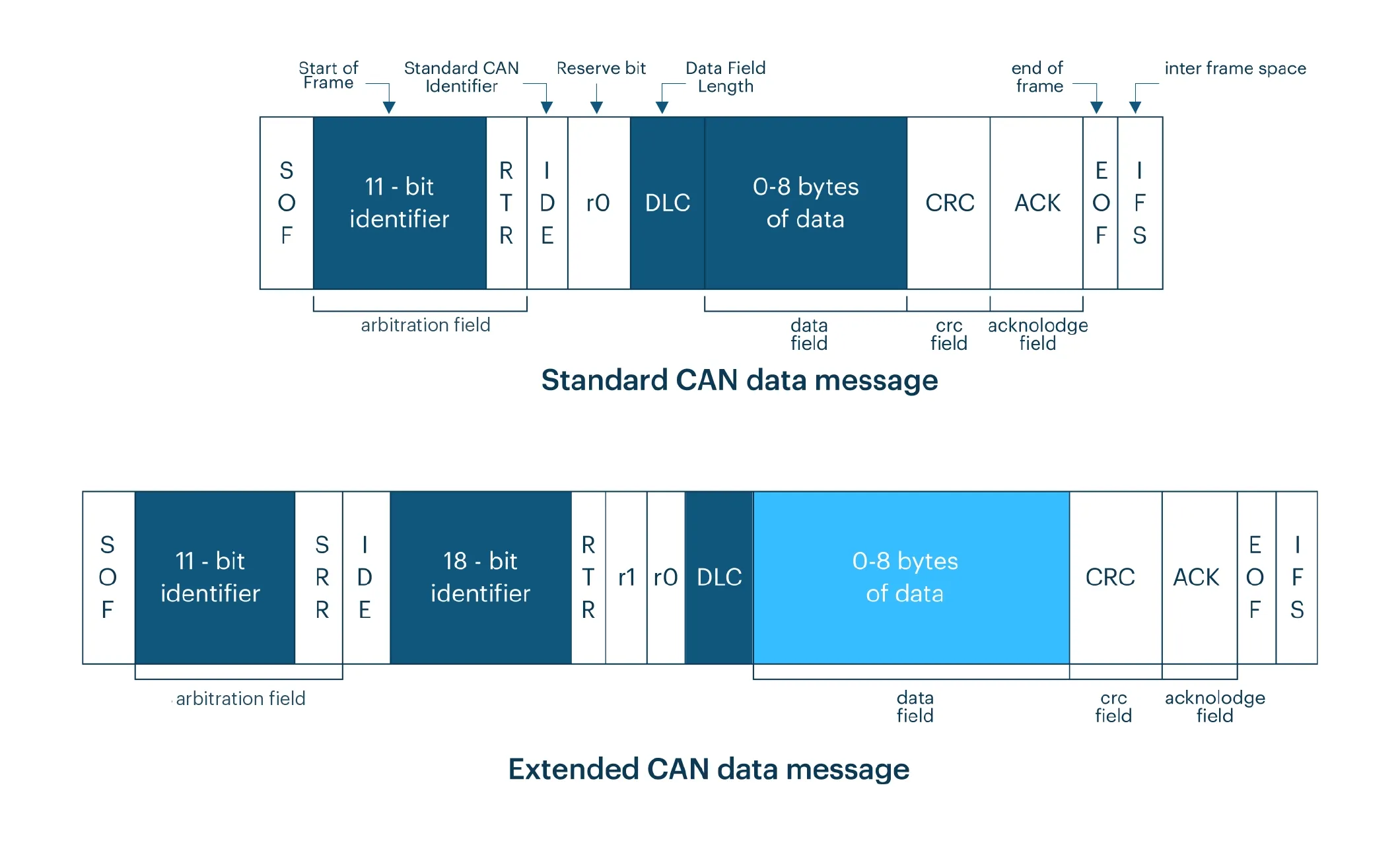
The image illustrates the structure of a standard CAN bus message format, detailing the components that make up a frame in the CAN bus system:
Start of Frame (SOF)
The SOF is a single dominant bit that marks the beginning of a message frame. It is used to synchronize all nodes on the CAN network to the beginning of a message, ensuring that each node starts interpreting the message at the correct point.
Arbitration Field
- 11-bit Identifier: Identifies the message’s priority. In CAN protocol, lower numbers have higher priority. This identifier is crucial in the arbitration process, where, if two nodes transmit simultaneously, the node with the higher priority (lower numerical value) wins the arbitration, and the other node automatically stops transmitting.
- RTR (Remote Transmission Request): A single bit indicating whether the frame is a Data Frame (dominant bit) or a Remote Frame (recessive bit), used to request the transmission of a Data Frame with the same identifier.
- IDE (Identifier Extension): In a standard frame, this bit is always dominant, indicating an 11-bit identifier.
Control Field
- r0 (Reserve Bit): A reserved bit, usually set to 0.
- DLC (Data Length Code): A 4-bit field specifying the number of bytes of data in the Data Field (0 to 8 bytes). This doesn’t affect the frame size directly but indicates how many bytes follow in the Data Field.
Data Field
Contains the actual data being transmitted, ranging from 0 to 8 bytes. The length of this field is indicated by the DLC in the Control Field.
CRC Field
Contains a Cyclic Redundancy Check code used to detect errors in the transmitted frame. This powerful type of checksum covers the frame from the Start of the Frame to the Data Field, ensuring message integrity.
Acknowledge Field
- ACK Slot: The transmitter sends a recessive bit, and the receiver sends a dominant bit if it received the frame correctly.
- ACK Delimiter: A recessive bit, providing a bit of space before the end of the frame.
End of Frame (EOF)
A sequence of seven recessive bits marking the end of a CAN frame, which provides a clear distinction between consecutive CAN frames and recovery space for nodes that lost arbitration.
Inter Frame Space (IFS)
A sequence of three recessive bits separating consecutive CAN frames, allowing time for other controllers on the network to prepare to respond or initiate messages.
Each of these components plays a crucial role in ensuring reliable, orderly, and efficient communication over the CAN network.
Frames Used in Various CAN Bus Functions
In the Controller Area Network protocol, different frame types serve various functions, each critical for maintaining efficient and robust CAN communication. Here’s a breakdown of the four primary frame types:
Data Frame
Used for transmitting data from the sender to the receivers, it’s the most common message type on a CAN bus interface. The Data Frame includes:
- Arbitration Field: An 11-bit or 29-bit identifier with a dominant RTR bit, indicating message priority. Lower identifier values have higher priority, enabling non-destructive bus arbitration during message collisions.
- Data Field: 0-8 bytes of data.
- CRC Field: A 16-bit checksum for error detection.
- Acknowledgment Field: Used to confirm successful message reception.
Remote Frame
Used to request the transmission of a Data Frame with the same identifier. Often used when a device requests data from another device. This frame has:
- A recessive RTR bit, differentiating it from a Data Frame, with no Data Field.
- Upon receiving a Remote Frame, the node with the matching identifier sends the corresponding Data Frame.
Error Frame
A special message transmitted when a node detects an error in a message. This maintains network integrity by ensuring all nodes are aware of errors. The Error Frame:
- Violates the standard CAN frame format so all nodes can detect the error.
- When detected, the node transmits an Error Frame, prompting other nodes to recognize and respond to the error, halting normal communication briefly, and causing the faulty message to be retransmitted.
Overload Frame
Transmitted by a node that is too busy to process further messages, introducing a delay in transmission. Structurally similar to an Error Frame, the Overload Frame is used to manage timing and ensure nodes aren’t overwhelmed by messages, helping control communication flow on the bus.
Integrating the Frame Types in CAN Bus Functionality
The interplay of these frame types within the CAN protocol ensures robust communication through:
- Arbitration: During simultaneous message attempts, the CAN bus arbitration mechanism allows the message with the highest priority (lowest identifier value) to proceed first, without message loss.
- Error Handling: The rigorous error detection (via the CRC and acknowledgment fields) combined with the error frame system allows for immediate correction, enhancing network reliability.
- Data Request and Response: The use of data and remote frames facilitates a request-response communication pattern, useful for sensor/actuator management where a controller can request data from sensors regularly.
- Network Management: Overload frames help manage times when nodes become too busy, preventing data loss by ensuring nodes are prepared to receive new data.
These mechanisms enable the CAN bus protocol to function efficiently in environments requiring high reliability and real-time capabilities, such as automotive systems, industrial automation, and more complex IoT implementations.
Features of CAN
Multi-master Configuration
CAN bus use a multi-master broadcast serial bus standard for communication between devices. For example, in automotive applications, both the engine control unit and the airbag sensor can send data to initiate actions. Devices on a CAN network communicate based on identifiers that determine the priority of messages and execute actions accordingly.
Error Detection
The CAN bus protocol has sophisticated error detection and correction capabilities. It can detect errors, such as bit errors, frame errors, and acknowledgment errors, enhancing reliability and robustness in environments with electrical interference and mechanical stress. Built-in error detection and handling mechanisms ensure communication reliability. For example, if a transmission error occurs in an ABS sensor signal, the system automatically retries sending the signal.
Reduced Wiring
A single CAN bus can replace multiple wires that would otherwise connect each component directly. The typical network topology used in CAN bus systems is a line topology with terminators at each end to prevent signal reflections. However, star topologies are also used when necessary. By reducing wiring needs, modern vehicles utilize vehicle CAN ubs systems to connect engine management systems, which helps reduce complex wiring harnesses.
Real-Time Capability
CAN allows for high-speed data transmission up to 1 Mbps, although the speed may decrease as the bus length increases. The standard frame size allows for transferring small packets of data (up to 8 bytes per frame), making it highly efficient for real-time applications. For instance, in factory automation, the CAN bus protocol enables real-time control of robotic arms for assembly tasks.
Limitations of CAN in IoT Applications
Limited Data Bandwidth
CAN bus is designed for transmitting small data packets (up to 8 bytes per frame) as defined in the ISO 11898-1:2015 standard, detailing the data link layer and physical signaling of the Controller Area Network (CAN). This limitation makes CAN less suitable for IoT applications requiring the transmission of larger data volumes, such as multimedia or extensive sensor data aggregation.
Low Speed
The maximum standard speed on a CAN network is 1 Mbps, which decreases with increased network length. For many IoT applications, especially those requiring real-time high-data-rate communication across a broader network, this speed becomes insufficient.
Scalability Issues
Controller Area Network supports a limited number of nodes. Nodes are individual electronic control units (ECUs), sensors, and actuators communicating over the CAN bus network. This limitation restricts scalability, making it challenging to integrate more devices in large-scale IoT deployments due to constraints like electrical loading.
Lack of IP Support
CAN network does not inherently support IP, which is a backbone for IoT communication. This lack of IP support complicates the integration of CAN communication systems with the Internet or other IP-based networks, often requiring additional gateways or protocol converters.
What is Virtual CAN?
Virtual CAN, often referred to as "vCAN" or "SocketCAN" in the context of Linux operating systems, is a software-based approach to CAN communication. It allows for the development, testing, and simulation of CAN bus applications without requiring physical CAN hardware.
The purpose of Virtual CAN is to emulate the behavior of a real CAN network, allowing developers and testers to write and test their software without needing any specific physical hardware for the CAN protocol.
Virtual CAN is closely associated with SocketCAN, a set of open-source CAN drivers developed by Volkswagen Research for the Linux environment. Its integration into the Linux kernel has made it a standard part of many Linux distributions, facilitating CAN network communication via software.
SocketCAN abstracts CAN protocol details into the socket interface, familiar to developers working with IP networks. This abstraction allows applications communicating over Controller Area Network to be developed similarly to applications using standard TCP/IP networking. Officially merged into the Linux kernel around 2007, SocketCAN provides a robust framework for developing CAN-based applications.
Virtual CAN Network Interface in SocketCAN
Within SocketCAN, a virtual CAN network interface can be created that simulates a real CAN network interface. This feature allows the development and testing of CAN applications without any physical CAN bus hardware. Developers can create multiple virtual CAN bus interfaces, configure network conditions, and simulate various network topologies and traffic patterns.
Advantages of Virtual CAN in IoT Applications
Reduced Hardware Requirements
Virtual CAN eliminates the need for a physical CAN bus interface during the initial phases of software development and testing. This can lead to significant cost savings, especially in large projects where multiple testing setups might otherwise be required.
Quick Setup
Setting up a virtual CAN environment is quicker and easier than arranging physical hardware, facilitating rapid prototyping and iterative development, and allowing developers to quickly test ideas and changes.
Controlled Testing Environment
Virtual CAN provides a controlled environment to test how IoT devices interact over a CAN network. This control is crucial for deterministic testing and debugging.
Tool Integration
Virtual CAN can be integrated with other software tools and environments, enhancing development and testing. For example, it can be used with network simulators, performance analyzers, and automated testing frameworks.
Common Use Cases for Virtual CAN (vCAN)
1. Automotive Systems Development
ECU Software Testing
In automotive IoT, software for Electronic Control Units (ECUs) requires rigorous testing. Virtual CAN enables developers to simulate and test ECU software interactions over a CAN network without needing a full vehicle setup, which accelerates the development and testing process.
Advanced Driver-Assistance Systems (ADAS)
Developers of ADAS technologies use virtual CAN bus interfaces to simulate complex vehicle sensor networks, ensuring software reliability before deployment in actual vehicles.
2. Industrial Automation
Machine Control Systems
Virtual CAN is applied in developing and testing control systems for machinery in industrial settings. Engineers can simulate a network of sensors and actuators to optimize control algorithms and system responses without disrupting production.
Predictive Maintenance
For IoT devices that monitor machinery health, Virtual CAN simulates scenarios where device readings indicate potential failures, enabling testing of automated alerts and system shutdowns.
3. Smart City Applications
Traffic Management Systems
Virtual CAN aids in developing traffic control systems that rely on networks of sensors and signals. By simulating traffic flow and signal timing, developers can optimize algorithms for reducing traffic and improving emergency response without requiring real-world trials.
Public Transport Networks
Virtual CAN enables development of communication systems for public transportation, ensuring seamless integration of bus and train management systems with traffic controls and passenger information systems.
4. Agriculture Technology
Farm Equipment
In precision agriculture IoT applications, Virtual CAN simulates networks that connect tractors, drones, and sensors. This supports software development for optimizing planting, watering, and harvesting based on real-time data.
5. Healthcare Devices
Medical Monitoring Systems
Virtual CAN is employed in developing networks for medical devices to reliably transmit patient data to monitoring systems, ensuring these devices meet the critical requirements of real-time health monitoring.
6. Home Automation
Smart Home Systems
In smart home technology, Virtual CAN allows simulation of interactions among various home automation devices, such as security systems, lighting, and HVAC systems, ensuring effective network communication.
7. Energy Systems
Smart Grids
Virtual CAN is essential for testing communication protocols in smart grids, where devices must effectively communicate to balance loads and maintain energy efficiency across extensive networks.
Cavli Connectivity Modules with Virtual CAN
The C10QM and C20QM are LTE Cat 1 and LTE Cat 4 modules for IoT and M2M applications. They are engineered to target OEMs who intend to develop complex connected solutions with additional features like Virtual CAN and transceiver support for Bluetooth and WiFi.
With Virtual CAN, it has become easier to eliminate physical restrictions on hardware and leverage the CAN bus protocol to make it expandable and send more data packets to expand its transmission capacity in Automotive and industrial processes.
Implementing virtual CAN emulates the aspects of the physical CAN network in a software environment. It allows extensive testing and development without the physical bus. It simulates how data travels across the network and how effectively it reaches its destination nodes. Virtual CAN can simulate the sending of maximum data to destination nodes, testing the network’s capacity and the robustness of data handling under various conditions.
Closing Notes:
vCAN is set to become a vital component in the future of IoT, addressing the limitations of traditional CAN systems and offering scalable, cloud-ready solutions. By empowering industries to push the boundaries of connected devices, vCAN provides the reliability, scalability, and flexibility needed to build smarter, more efficient systems. As technologies like 5G continue to develop, vCAN's role will become even more critical, solidifying its position as the backbone of the IoT revolution.
Go Beyond and Explore
How Does Virtual CAN (vCAN) Enhance the Development and Testing of CAN-Based Networks?
Virtual CAN (vCAN), implemented via SocketCAN in Linux environments, provides a software-based emulation of physical CAN interfaces. It enables engineers to simulate CAN bus networks, facilitate software testing without the need for hardware, and prototype communication protocols in a controlled virtual environment. This approach allows for rigorous testing, including network load, frame arbitration, and error handling, crucial in automotive, industrial, and IoT applications.
What Are the Steps to Configure and Activate a Virtual CAN Interface on Linux?
To create a Virtual CAN device, execute the following commands:
sudo ip link add dev vcan0 type vcan
sudo ip link set vcan0 up
This setup creates and activates a Virtual CAN interface named vcan0 using the
ip utility, which is essential for simulating CAN communication. SocketCAN abstracts
the CAN protocol details, allowing CAN frames to be managed as IP packets via the familiar Linux
socket interface, thereby enhancing compatibility with existing network applications.
What Are the Primary Technical Advantages of Virtual CAN in Automotive and Industrial IoT Development?
Virtual CAN (vCAN) offers a range of benefits, including cost-effective testing without physical hardware, rapid prototyping, and the ability to simulate complex CAN network topologies. It supports the emulation of multi-node CAN communication, enabling developers to evaluate network performance under various conditions, detect protocol errors, and validate control logic in Electronic Control Units (ECUs) and real-time industrial systems.
How Can Virtual CAN Devices Be Integrated with Diagnostic and Simulation Tools?
Virtual CAN interfaces are compatible with diagnostic tools such as can-utils, which provides utilities like candump and cansend for monitoring and transmitting CAN frames. These tools enable engineers to analyze bus traffic, simulate message transmission, and stress-test applications in a virtual environment. By configuring source and destination interfaces, engineers can emulate scenarios such as CAN traffic bridging, frame redirection, and network fault injection for comprehensive protocol validation.
What Are the Critical Applications and Simulation Capabilities of Virtual CAN Networks?
Virtual CAN (vCAN) is extensively used for simulating vehicle ECU interactions, validating advanced driver-assistance systems (ADAS), and optimizing real-time automation in industrial IoT networks. It facilitates controlled testing scenarios, such as error frame injection and priority arbitration, and supports robust simulation of sensor-actuator communications. This enables precise validation of system resilience, latency, and fault tolerance, essential in high-reliability environments like automotive control networks and industrial automation systems.
Author

Drishya Manohar
Sr. Associate - Content Marketing